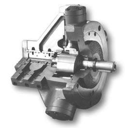
The
body of the engine has a flat surface,
which is perfectly perpendicular to
the rotation axis of the movement transmission
shaft, which lays on the flat side of
the assembly clamp; and on the top,
it has a calibrated diameter for the
centered adjustment. The bores on the
body are made for studs of advisable
diameter. The adjustment tolerance for
the assembly clamp is of (H6) whereas
for the diameter of the engine cover
it is (H5).
How
to place the engine
When the engine is mounted horizontally,
it is appropriate to place the drainage
bore at the highest position of the
engine, in order to keep its body full
of oil and thus lubricating the moving
parts.
In case the engine is mounted vertically
with the movement transmission shaft
pointing upwards, it should be appropriate
to consult the engine vendor about the
best drainage connection in order to
achieve a right oil flow.
If the engine is placed with the movement
transmission shaft vertically pointing
downwards, this connection does not
need extra care, since everything inside
the engine is lubricated by the oil.
Anyway, it is recommended to ask the
vendor for necessary advice. The engines
are provided with oil connection clamp,
(except for the axial connection engines)
with inlet and outlet holes, with a
screw for pipe or hose plugs that allow
dismounting through screws without damaging
the thread of these plugs due to successive
assembly and dismounting. Be sure of
not reducing the diameter of the connections
with non-standardized plug adaptors
or connectors.
Start-up
In order to achieve the good operation
of the engine, it is recommended
to use a good-quality hydraulic
fluid, being properly filtered.
For the engine start-up, you should
fill the body with oil, -it is
not necessary to set it in motion-
using 10 micron filters and keeping
a fluid circulation pressure not
higher than 70 kg/cm² (50
atmospheres), until the complete
removal of impurities is achieved.
This should be done whenever an
element in the hydraulic circuit
is placed or replaced. After half
an hour in motion, the filter
should be changed and the operation
system should be set back. You
should not forget that the drainage
connection placed at the highest
point in the engine cannot be
connected with exhaust pipes;
in any case it may be connected
with other drainage connections,
so that the pressure in the pipe
does not exceed the atmospheric
pressure.
The oil pressure inside the body
shall not exceed 0,7 Kg/cm²
(0,68 atmospheres).
The fluid inlet and outlet connection
pipes should be properly adjusted
for an oil speed of 6 m/sec. To
filter the oil, it is recommended
to use grids of 25 microns for
210 Kg/cm² and of 80 microns
for 150 Kg/cm². It is always
convenient to install magneto-
mechanical filters in order to
collect ferrous particles.
Maintenance
In normal operation conditions, the
engine does not require intensive maintenance,
but it is necessary to check the fitting
frequently, as well as the alignment
of the movement transmission shaft with
the coupling and to change the fluid
contained in the body, by the drainage.
This will be done after the first 100
hours and the interference tension in
the fixing studs shall be checked. (If
there exists looseness, the interference
of the stud should be checked more frequently).
Every 500 hours the screws that make
up the component parts of the engine
will be tightened. Should a screw be
found broken, all the screws that fixed
said part shall be changed.
The manufacturer of the filter will
establish the replacement or cleaning
of the filters, and determine the appropriate
capacity and size.
Before opening a hydraulic engine, verify
that there exists a well-founded reason.
Very frequently, failures are produced
by elements in the hydraulic circuit
and not by the engine itself.
The speed reduction may be caused by
problems in the pump, leaks in the circuit
or fluids with a viscosity different
from the one appropriate for the operating
conditions. Some problems in the pressure
control valves or failures in the pumps
may reduce the torque produced by the
engine. The lack of synchronization
in the rotation of the movement transmission
shaft may be caused by the presence
of fluid in the circuit; this may also
cause knocking and swinging in the pipes,
and many times this is thought to be
caused by the engine. The speed reduction
may also be caused by internal leaks
through the contact surfaces in motion;
in such case you should check the drainage
outlet and the pressure inside the body.
As a consequence, there is also a reduction
in the torque delivered by the engine.
The engine usually produces a weak puff-puff
noise, which does not mean that it has
a problem, unless it were stronger.
Fluid draining out of the engine show
damage in the seals, which will have
to be necessarily changed.
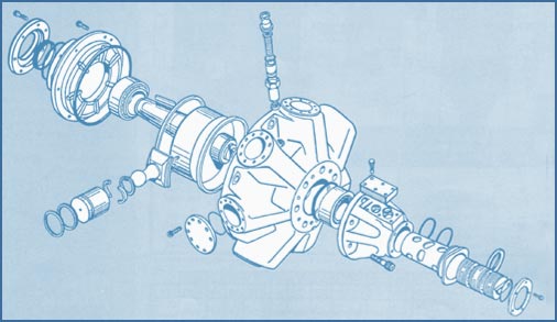
Engine
assembly
The body of the engine should be placed
with the cavity facing upwards. First,
you have to tighten the distributor
valve rings with a 0,1 to 0,2 millimeters
light. Then, place 12 rings in the distributor
valve and with a ring-press introduce
them into the sleeve, so that the coupling
slot with the roller stays inwards,
passing through 14 millimeters from
below the levelness.
You should always hammer with a rubber
or aluminum sledgehammer.
Invert the engine position.
Through the sleeves where the cylinder
covers will be placed, introduce the
pistons with their corresponding nylon
rings inside the cylinders.
From the inner side of the engine, mount
each piston-brake shoe set with the
corresponding fixing sockets of the
piston and the lock (seeger).
Put them inside a brake shoe fixing
ring and fit the coupling roller into
the distributor valve, locating first
the mark on the valve (determined by
points, an arrow or a cross) which shall
coincide with the part of the crank
shaft furthest from its center. Mount
the crankshaft, put the sets piston-brake
shoe close to each other, fitting them
inside the lower ring, and then, fit
the other brake shoe fixing ring. Place
the bearing holder top, tightening evenly
all the screws until the torque limit
of these screws, together with the seal
holder top. With a probe, check that
the crank shaft does not have axial
play; in case there exists play, slide
the top off again and shape with a lathe
the face that lays against the engine
body so that the top is tightened 0,03
millimeters.
EXAMPLE: Pushing the lever, the probe,
fixed to the engine body as fixed point,
registers a variation of 0,05 millimeters
of play in the crankshaft. To correct
it, shape with a lathe 0,08 millimeters
of the top support, having in such a
way, a 0,03 millimeters adjustment.
Finally, push the distributor valve
so that it stops against the crankshaft
and screw the valve top and the cylinder
tops.
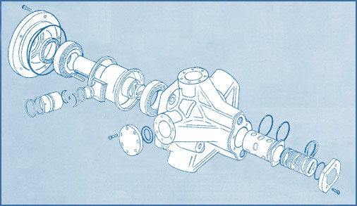
Engine
dismounting
It is convenient to start dismounting
the engine from the side where the shaft
stands out.
Once the fluid connections are taken
off, the bolts are unscrewed from the
roller holder top.
The screws are put in the two bores
with screws; which once tightened, will
untie the roller holder top. The good
condition of the roller chamber track
and rubber seal, both attached to the
top, can thus be observed.
Release the top from the upper brake
shoe fixing ring. If you move the crankshaft
axially, you will split the sets brake
shoe-piston.
Lift the brake shoes some millimeters
and they will be released from the brake
shoe-piston holder ring inside the corresponding
cylinders. Remove the crankshaft, being
careful about its position in relation
to the distributor valve, since its
location may affect the rotation direction
of the engine. If you rotate the crank
shaft 180 degrees with respect to the
position of the distributor valve, the
rotation will be inverse while keeping
the same fluid inlet and outlet connection
positions. The clamping between the
distributor valve and the crankshaft
is performed by a coupling roller with
two anchoring positions. Once you have
removed the crankshaft and the coupling
roller, remove the brake shoe-piston
set from the corresponding cylinders.
The brake shoes are bound to each other
by means of flexible safety rings.
You should be careful about not mixing
the brake shoe-piston set with another
set, since this may cause a parts molding,
where the set change may be harmful.
Watch the contact surfaces between the
joint and the piston; if there exists
an odd wear or scratches, a change or
reconditioning will be required.
Do not split the joint from the brake
shoe.
Inside the brake shoe there is a bronze
jet, which will be removed with a screwdriver.
Check that the 0,5 millimeters bore
that passes through it is not blocked.
Below the jet there is a powdered bronze
filter, which will be cleaned or replaced
by a new one, in case it is full of
impurities. The contact surface between
the brake shoes and the crankshaft shall
be in perfect conditions. If there were
some scratches, rectify the crankshaft
and fix the brake shoe. Remove the cylinder
covers and check that the inner surface
does not have scratches or uneven play.
Change the nylon rings of the pistons,
the seal rings corresponding to the
pistons and the rings corresponding
to the pistons that expand the nylon
rings.
Turn the engine over, remove the screws
from the distributor valve top, and
with a rubber sledgehammer knock the
distributor valve in order to move it
inside the engine and take it away.
Watch the distributor valve shirt surface
which is fastened to the body. In case
there appear deep steps caused by the
distributor valve rings, polish the
surface and change the metallic rings
together with the distributor valve,
or change the shirt and leave the valve
(rectified) and the rings.
Once the dismantling has been fulfilled,
wash all the elements with the proper
solvent.
First, change all the seal rings from
the dismounting and even those that
are still in engine parts that were
not dismounted. Wash the rollers properly
and check their perfect condition.
Assembly
clamp
The diameter of the clamp to assemble
with the engine shall not have a tolerance
higher than 0,15 mm. with the assembly
diameter and an eccentricity higher
than 0,13 mm.
Drainage
Before
setting the oil-dynamic engine
in motion, fill the crankshaft
box with the same fluid you use
in the circuit, pouring it in
through the drainage bore existing
in the body.
If the engine is mounted with
the shaft horizontally, the output
for the fluid drainage that returns
to the tank will be placed in
the highest point, never under
the central line.
See figure 1.
If the engine is placed with the
shaft facing downwards, there
will not be special requirements
for the drainage location.
See figure 2.
If the engine is placed with the
shaft facing upwards, first you
will have to turn the engine with
the shaft downwards, and then
you will fill the body with the
fluid. Then clamp a flexible connection
to the drainage bore.
Keeping the rear end connection
in a high position, the engine
is mounted in its operation position,
and the drainage outlet is connected
to a storage tank, that is over
the engine (see figure 3), or
to a fixed pipe higher than the
engine, so that the content of
oil in the body is not emptied
(see figure 4). In no case, can
the engine drainage pipes be mixed
with exhaust connections; on the
contrary, they have to head directly
for the tank. They cannot be inserted
through below fluid level. Check
that the pipe diameter is appropriate
and that the section does not
have blocks, or sharp curves.
The drainage fluid pressure shall
not exceed 0,7 kg/cm², in
the engine oil pan.
Fluid
recommendations
When considering the features of the
fluid, you should consider mineral oil,
without detergent, with rust free and
foam free agents, and emulsifier additives.
It should be stable considering its
viscosity under engine operation temperature,
and it should contain the non-wear additives
in order to avoid friction. In the circulation
throughout the engine, the fluid does
not have to exceed 70ºC of temperature,
since it may lose its lubricating properties
and damage the rubber seals quality.
Take into account that the oil viscosity
varies in relation to the temperature,
therefore we recommend a viscosity ratio
of 16 to 21 cSt for operation temperatures
under 10 degrees; from 21 to 37 cSt
for temperatures upto 50 degrees and
a viscosity ratio of 37 to 80 cSt for
temperatures higher than 70 degrees.
These values are approximate therefore
they may vary due to operation pressure.
Filtration
The
working duration of the elements of
a hydraulic system (including the Hydraulic
engine) is firmly related to the efficiency
of the filtering system and to its capability
of holding particles, bigger than the
dimensions pre-established, that may
eventually appear in the fluid. It is
advisable to use filters of 25 –
30 microns for open circuits and filters
of 10 – 15 microns for closed
circuits. As the filters gradually accumulate
foreign bodies, they reduce their efficiency;
therefore it is very important to clean
them or replace the filtering elements
(cartridges).
It is not possible to determine the
filter duration, especially when this
is part of a circuit that starts operating
for the first time, due to the possibility
of having more or less quantity of impurities
in the system.
A good procedure is to replace all the
filtering elements after the first four
hours of operation, and then follow
the manufacturer’s suggestions.
Operation
temperature
The fluid temperature in the oil pan
cannot exceed 70 degrees.
If this temperature were higher, a temperature
pipe of suitable dimensions should be
installed in the circuit in order to
eliminate the excess of temperature.
You should bear in mind this suggestion
when assembling the hydraulic engine.
In case any unexpected failure aroused
during the start-up or later operation,
having followed the abovementioned instructions,
consult our technical office in order
to solve the problem as soon as possible.
EQUIPOS
CID HNOS. S.A.C.I.F.I. WILL NOT CONSIDER
THE WARRANTY VALID IF THE ENGINE WAS
DISMOUNTED OR HANDLED WITHOUT THE PRIOR
AUTHORIZATION OF THE COMPANY.