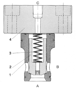
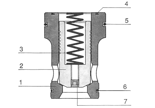
Cid
cartridge elements are insertional
modular valves type 2/2 pilot operated
used for command functions and regulation
of hydraulic circuits. They are made
up of a body (1), a float (2), a lock
coil (3), and a lock top (4), which
has the function of supporting the
passage for the pilotage and fixing
the set.
The building of this top varies according
to the function to be performed by
the valve. With this type of elements
it is possible to build systems that
fulfill the following functions:
- Directional valve
- Retention valve
- Ordinary retention valve
- Piloted retention valve
- Electro-piloted retention valve
- Pressure control valve
- Relief valve
- Electro-piloted relief valve
- Proportional electro-piloted relief
valve
- Sequence valve
- Flow control valve
CIRCUIT
WITH CARTRIDGE VALVES
Besides the abovementioned function (directional),
the cartridge components enable the performance
of complete hydraulic circuits. For a given
application in a circuit with conventional
elements, the valves are connected in parallel
or in series, depending on the control function
required, such as retention valve, flow control
valve and pressure control valve. For a distributor
channel, cartridge valves are required, where
all the command functions are carried out
by pilot valves; whereas cartridge elements
on the power line are used as logical elements.
The cartridge performs multiple functions,
allowing a saving on valves on the line, connection
sections, and load loss, which are thus proportionally
reduced according to the circuit complexity
and the size of the cartridge.
The above-shown sample represents the realization
of the command of a usage channel by means
of a locked center distributor, a regulation
to delivery (consumption) with free return
and a pressure limiting device. With respect
to the circuit with valves, during the cartridge
execution, the fluid regulation function is
carried out by the C1 cartridge, provided
with stopcock opening limiting device. The
C2 cartridge works as a pressure limiting
valve. When the cartridge pilotage reliefis
performed through a retention valve and a
pilot valve, the cartridge itself replaces
the distributor, connecting the delivery to
the exhaust. In the case of more complex circuits,
the saving on valves usage is more relevant
than in those obtained in the described sample.
- Saving on valves on the line due to multiple
functions of the cartridge.
- Maximum reliability (working assurance)
- Volume and weight reduction of the set,
up to 50%.
- High passage and reduced load lost, less
hydraulic fluid warming.
- Short response and regulation time.
- Absence of pressure peaks. The cartridges
are piloted according to pressure.
- Smooth and precise response. Throttle and
regulating screws (opening limiting device)
take part in the regulation.
- Low maneuvering noise favored by the block
assembly.
- Uniformity of the elements in the circuits,
e.g. command electro-valves of the same nominal
size in the whole circuit.
- Easy maintenance, minimum quantity of elements
in motion.
- Two models in five different sizes:
VC-16 / VC-25 / VC-32 / VC-40 / VC-50
TVC-16 / TVC-25 / TVC-32 / TVC-40 / TVC-50
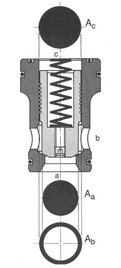
Surface
ratio of cartridge valves.
The
stopcock position depends on the value
of the pressure of the inlet A, B,
C and on the lock coil stress.
The active surfaces are related according
to the dimension of each area, always
considering the ratio Ac= Aa + Ab,
where Ab may be = 0.
The cartridges are built with three
values of ratio: - A = 1:1 . B = 2:1 . C =
14,3:1
The fluid may either flow through
the cartridge from A to B or from
B to A, whether the pressure ratio
between A and B allows it or not,
or without the C pilotage pressure.
If a pilotage pressure is exerted
on the C connection, the stopcock
float hermetically seals the passage
between A and B, preventing the fluid
circulation. The cartridge elements
only function in relation to the pressures
ratio.
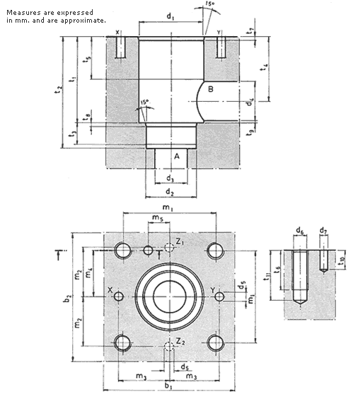
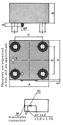
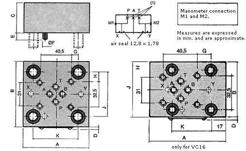
Cartridge
valves installation dimension according
to DIN 24342 standards