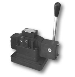
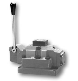
Board
assembly. Models: 17-70, 75 and 100. Size:
CETOP 7 NG 16 and CETOP 8 NG 22 and NG 25.
Board
assembly manual command valves are produced
in two, three and four tracks and in three
sizes depending on the different flow volumes:
- HM-17-70-#-#-P model functions with flow
volumes up to 300 l/min and a pressure of
up to 280 Kg/cm² depending on the fluid
and kind of rod.
- HM-17-75-#-#-P model functions with flow
volumes up to 350 l/min and a pressure up
to 210 Kg/cm² depending on the fluid
and kind of rod.
- HM-17-100-#-#-P model functions with flow
volumes up to 530 l/min and a pressure of
up to 280 Kg/cm² depending on the fluid
and kind of rod.
- Manual-lever command.
- Easy combination between manual command
and a hydraulic signal of the system.
- Assembly board CETOP 4.2-4-07-320 e/o UNI
ISO 4401-AD-07-4-A, according to CETOP 8 NG
22 and CETOP 4.2-4-08-320 e/o UNI ISO 4401-AE-08-4-A
respectively.
- Individual plates standardized by the following
screws:
PM-SHP-70-75-T > 3/4” NPT Screw.
PM-SHP-70-100-T > 1” NPT Screw.
PM-SHP-75-100-T > 1” NPT Screw.
PM-SHP-100-100-T > 1” NPT Screw.
PM-SHP-100-125-T > 1”1/4 BSPT Screw.
HM-17-70-#-#-P
HYDRAULIC
SCHEME
FIXING:
4
Whitworth Screws Ø
1/2”x2”1/2.
Communication holes A, B,
P, T, Ø 23. X, Y,
Ø 8.