Volver al menú anterior
  Stop or exhaust valve with directional valve  
  Line and board assembly. Size 3/8”, 1/2”, 3/4” and 1” 1/4 BSPT  
 
 
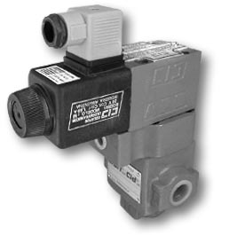
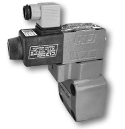
The exhaust valves for decompression are used in a system where it is necessary to produce a fluid exhaust or block in that section, without the equipment pressure. This valve also has a directional valve model SH-4-12- ##, used as an actuator, which may be activated by means of an electrical signal.
The more typical cases in which they are applied are the following:
Pump exhaust in a high and low circuit, simple effect cylinder descent without having the equipment in motion, activate or deactivate part of the system.


- It is supplied in Normally Open and Normally Closed.


  SEE SOLENOIDS
   
 
  VF-L-##-E-##-# (Line assembly)  
 
   
HYDRAULIC SCHEME
ORDER CODE:


SIZE A B C D E F G H I CONEX.
P and T
WEIGHT
(Kg.)
32 37 152,5 189,5 129 40 105 79 57 118,5 S Ø 3/8" NPT 3,9
75 153,5 190,5 130 45 105 91 80 59,5 S Ø 3/4" NPT 4,350
125 172,5 209,5 149 64 105 125 96 59,5 S Ø 1" 1/4 BSPT 6,750


  VF-P-##-E-##-# (Board assembly)  
 
   
FIXING:
  Size: 32:
4 Whitworth Screws Ø 1/2”x2”1/2.
Size: 75:
4 Whitworth Screws Ø 1/2”x2”3/4.
Size: 125:
4 Whitworth Screws Ø 3/4”x3”1/4.
BOARD ASSEMBLY:
  PM-RP-P-32-#-T
PM-RP-P-75-#-T
PM-RP-P-125-#-T
HYDRAULIC SCHEME
ORDER CODE:


SIZE A B C D E F G H I J K M N O R CONEX.
P and T
WEIGHT
(Kg.)
32 37 162,5 54 199,5 22 25,5 82 54 41 118,5 46 Ø 13,5 Ø 20 139 29,2 Ø 11 4,6
75 170,5 66,5 207,5 27,5 38 104 70 105 59,5 54 Ø 13,5 Ø 20 147 39,5 Ø 23 6,5
125 184,5 66,7 221,5 30,2 44,5 132 92,5 105 59,5 64 Ø 20 Ø 26 161 44 Ø 28 9,650


  Volver arriba


Diseñado por 01. Visite nuestro sitio